Pneumatic Actuators
Pneumatic actuators are probably the most common type of actuator, because of their cheap and readily available power source, which is compressed air. Not only are they generally less expensive than electric or hydraulic alternatives, but they are also less complex in design and so are easier to maintain.
Pneumatic actuators are particularly suited to part-turn valves with their limited stroke requirements, however they can also be used for linear clos- ing valves. Pneumatic power is relatively easy to store and it is suitable for use when power sources are of a limited capacity or simply not available. Pneumatic actuators can be used on valves of most sizes.
Pneumatic Power Supplies
Pneumatic supply is generally compressed dry air, but designs are also available for natural gas. Compressor and accumulator design is a consideration when designing a network of pneumatically operated actu- ators to achieve an efficient system. Valve operating times are also a significant factor when determining the pneumatic capacity of the supply and the size of the tubing.
Types of Pneumatic Actuators
There are three basic types of pneumatic actuators, given below.
Diaphragm types. Diaphragm actuators are usually designed for linear motion, although it is possible to have rotary motion designs. Pneumatic actuators are usually attached to the body of the valve by means of a threaded yoke, which can be fitted with a pointer to indicate the position of the valve.
A exible plate diaphragm is held between two separate casings that are bolted together to form two airtight chambers. There are two independent air supplies to the chambers through which compressed air either can be introduced or can escape. As air is introduced into one chamber, this causes the diaphragm to ex and this motion either extends or retracts the actuator stem, which is attached to the closure element. The more air that is supplied the greater the movement of the stem.
In the single-acting design a spring is introduced to the opposite air chamber to assist the return of the diaphragm when the air pressure is lessened. This spring also acts as a fail-safe mechanism allowing the valve to return to an open or a closed position, when there is a power failure.
Direct acting is where the air pressure introduced forces the diaphragm and the attached valve stem down to the required location. Air failure will cause the stem to be retracted out of the valve body and open the valve, and make sure it remains open.
Reverse acting is where the air pressure introduced forces the diaphragm and attached valve stem up to the required position. Any loss of air pressure will allow the stem to move to the extended position and close the valve. The valve will remain closed until the air supply is reintroduced.
Direct acting for rotary valves is where the air pressure introduced forces the diaphragm and attached valve stem down and, according to its orientation, the valve will be either opened or closed.
Diaphragm valves are relatively cheap, of a basic construction, and easy to maintain. They are very well-suited for low thrust requirements in the lower-pressure piping classes.
Disadvantages of the diaphragm actuators of the linear design are that they can create height problems on smaller valves in restricted locations and on larger sized valves casings can become excessive in weight.
Piston type. Although not initially the first choice of pneumatic design, the piston actuator is becoming more commonly used as process con- trol becomes more sophisticated. This design consists of a cylinder that contains a sliding piston, which is sealed with elastomer O-rings. The actuator cylinder is attached to the valve by a cast yoke that allows for sufficient room on the stem to accommodate positioners and other accessories.
Piston actuators are usually double acting with an air supply to both chambers and a positioner to take the signal and supply or bleed air from the desired air chambers. Pistons generate a linear force that either can be transmitted directly to the actuator stem or has to be converted to a rotary force for use on part-turn valves. As most of the part-turn valves require only 90。movement, this can be achieved by one of the following.
1. A scotch yoke actuator (Figures 8-2a and 8-2b) consists of a piston, a connecting shaft, and a rotary pin.
2. A rack and pinion actuator (Figure 8-3) consists of a single or a double
piston that is coupled with an integral rack that drives the pinion.
3. Atrunnion/lever arm actuator normally comprises a simple trunnion mounted cylinder with a piston that acts directly upon a lever that is attached to the valve shaft.
4. A cam actuator (Figure 8-4) consists of double pistons connected by bars with a cam and shaft between them.
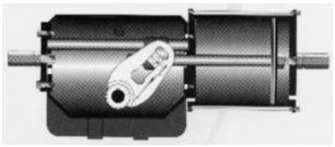
Figure 8-2. (a) Scotch Yoke Section
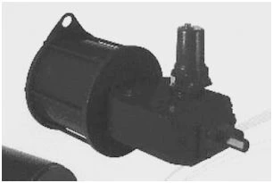
Figure 8-2. (b) Scotch Yoke

Figure 8-3. Drawing of Types of Rack and Pinion Actuators.

Figure 8-4. Drawing of Double Acting Cam Actuator.
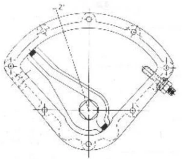
Figure 8-5. Drawing of a Vane Actuator.
Vane type . Vane actuators (Figure 8-5) are commonly used for quarter- turn (90。) applications. They comprise a piston type plate vane, within an airtight chamber, with an integral rotary shaft to produce the necessary torque to rotate the actuator stem. Compressed air is introduced into one of the chambers and air is exhausted from the opposite chamber, causing the vane to move and rotate the shaft.
The advantages of the vane design are low cost, basic design, few moving parts, and low maintenance. Its disadvantage is that, because of its very low torque values, it can only be used for low-pressure applications.
Advantages
To summarize, these are the advantages of pneumatic actuators:
1. Compressed air is convenient and relatively cheap to supply.
2. A piston is not self-locking and it can be used against a spring so it can be used for “single shot” emergency operation.
3. When air is in contact with heat, an increase in pressure caused by thermal expansion will assist the operation of the actuator.
4. Surplus air can be safely vented to the atmosphere.
5. The mechanical design makes it relatively cheaper than alternatives and easier to maintain.
Disadvantages
1. Because there is no kinetic energy it is not possible to deliver an initial “hammerblow” to unseat a wedge valve.
2. Air is a compressible medium and its ability to maintain a fix position is limited. This may result in drifting with both gate and buttery valves.
3. The design of the pneumatic actuator and the fact that it requires soft sealing rings means that there are temperature limitations and the unit must be equipped with adequate thermal insulation if there is a possibility that the actuator has to function during a fire.
4. Air motors are susceptible to seizure because of ingress of foreign material, or internal corrosion if the compressed air has not been sufficiently dried. This will greatly affect the performance of the actuator.
5. The consumption of air for pneumatic motors will be high and this demand is not always possible for the larger valves requiring higher torques.
Summary
The pneumatic actuator is possibly the most commonly used actuator, because of its advantages and the fact that accessories and spares are readily available. This type of actuator is also available in a variety of metallic materials of construction to suit the application and additional protective coats can be easily applied.
