Design Of Check Valves
Lift Check Valves
The check valves shown in Figure 4-1 through Figure 4-7 represent a cross section of the family of lift check valves.
Lift check valves have an advantage over most other types of check valves in that they need only a relatively short lift to obtain full valve opening. This lift is a minimum in lift check valves in which the flow passage at the seat is ring-shaped, as in the valves shown in Figure 4-4 and Figure 4-6. Lift check valves are, therefore, potentially fast closing.
In the majority of lift check valves, the closure member moves in a guide to ensure that the seatings mate on closing. However, such guiding also has a disadvantage in that dirt entering the guide can hang up the closure member, and viscous liquids will cause lazy valve operation or even cause the closure member to hang up. These types of lift check valves are therefore suitable for low viscosity fluids only, which are essentially free of solids. Some designs overcome this disadvantage, as in the valve shown in Figure 4-5, in which the closure member is ball-shaped and allowed to travel without being closely guided. When the valve closes, the ball-shaped closure member rolls into the seat to achieve the required alignment of the seatings.
The check valve shown in Figure 4-2 is specifically designed for appli- cations in which a low surge pressure is critical. This is achieved in two ways, first, by providing the closure member with a conical extension that progressively throttles the flow as the valve closes, and second, by com- bining the closure member with a dashpot that comes into play in the last closing moments. A spring to assist closing of the valve has been purposely omitted, as breakage of the spring was considered a hazard for the service for which the valve is intended.
The check valve shown in Figure 4-6 is designed for gas service only. Depending on flow conditions, the valve may serve either as a constant-flow check valve in which the valve remains fully open in service irrespective of minor flow fluctuations, or as a pulsating-flow check valve in which the valve opens and closes with each pulse of the flowing gas.
Constant-flow check valves are used after centrifugal, lobe-type, and screw compressors, or after reciprocating compressors if the flow pulsa- tions are low enough not to cause plate flutter. Pulsating-flow check valves are used after reciprocating compressors if the flow pulsations cause the valve to open and close with each pulsation. The valves are designed on the same principles as compressor valves and, therefore, are capable of withstanding the repeated impacts between the seatings. The manufacturer will advise whether a constant-flow or pulsating-flow check valve may be used for a given application.
The valves owe their operational characteristics to their design principle, based on minimum valve lift in conjunction with multiple ring-shaped seat orifices, low inertia of the plate-like closure member, frictionless guiding of the closure member, and the selection of a spring that is appropriate for the operating conditions.
The valve shown in Figure 4-7 is a combined lift check and stop valve. The valve resembles an oblique pattern globe valve in which the closure member is disconnected from the stem. When the stem is raised, the valve acts as a lift check valve. When the valve is lowered and firmly pressed against the closure member, the valve acts as a stop valve.
Lift check valves must be mounted in a position in which the weight of the closure member acts in the closing direction. Exceptions are some spring- loaded low-lift check valves in which the spring force is the predominant closing force. For this reason, the valves shown in Figure 4-1 and Figure 4-5 maybe mounted in the horizontal flow position only, while the valve shown in Figure 4-2 may be mounted in the vertical up flow position only. The valves shown in Figure 4-3, Figure 4-4, and Figure 4-7 may be mounted in the horizontal and vertical up flow positions, while the valve shown in Figure 4-6 may be mounted in any flow position, including vertical downflow.
Swing Check Valves
Conventional swing check valves are provided with a disc-like clos- ure member that swings about a hinge outside the seat, as in the valves shown in Figure 4-8 and Figure 4-9. Travel of the disc from the fully open to the closed position is greater than in most lift check valves. On the other hand, dirt and viscous fluids cannot easily hin- der the rotation of the disc around the hinge. In the valve shown in Figure 4-9, the closure member is an integral part of the rubber gas- ket between the valve body halves. It is steel-reinforced, and opens and closes by bending a rubber strip connecting the closure member and the gasket.
As the size of swing check valves increases, weight and travel of the disc eventually become excessive for satisfactory valve operation. For this reason, swing check valves larger than about DN600 (NPS 24) are fre- quently designed as multi-discswing check valves, and have a number of conventional swing discs mounted on a multi-seat diaphragm across the flow passage in the valve.
Swing check valves should be mounted in the horizontal position, but may also be mounted in the vertical position, provided the disc is prevented from reaching the stalling position. In the latter case, however, the closing moment of the disc, due to its weight, is very small in the fully open position, so the valve will tend to close late. To overcome slow response to retarding flow, the disc may be provided with a lever-mounted weight or spring loaded.
The check valve shown in Figure 4-10 is a double-discswing check valve with two spring-loaded D-shaped discs mounted on a rib across the valve bore. This design reduces the length of the path along which the center of gravity of the disc travels; it also reduces the weight of such a disc by about 50%, compared with single-discswing check valves of the same size. Coupled with spring loading, the response of the valve to retarding flow is therefore very fast.
Tilting-Disc Check Valves
Tilting-disc check valves such as the one shown in Figure 4-11 have a disc-like closure member that rotates about a pivot point between the center and edge of the disc and is offset from the plane of the seat. The disc drops thereby into the seat on closing, and lifts out of the seat on opening. Because the center of gravity of the disc halves describes only a short path between the fully open and the closed posi- tions, tilting-disc check valves are potentially fast closing. This particular valve is, in addition, spring-loaded to ensure quick response to retarding forward flow.
Reference may be made also to the valve shown in Figure 3-77 that can serve as a butterfly valve, a tilting-disc check valve, or a combined tilting-disc check and stop valve, depending on the design of the drive.
Tilting-disc check valves have the disadvantage of being more expensive and also more difficult to repair than swing check valves. The use of tilting- disc check valves is therefore normally restricted to applications that cannot be met by swing check valves.
Diaphragm Check Valves
Diaphragm check valves such as those shown in Figure 4-12 through Figure 4-15 are not as well-known as other check valves, but they deserve attention.
The check valve shown in Figure 4-12 consists of a perforated cone- shaped basket that supports a matching diaphragm. This assembly is mounted in the pipeline between two ranges or clamped between pipe unions. Flow passing through the cone lifts the diaphragm offits seat and lets the fluid pass. When forward flow ceases, the diaphragm regains its original shape and closure is fast. One application worth mentioning is in purge-gas lines, which feed into lines, handling slurry or gluey sub- stances. Under these conditions, diaphragm valves tend to operate with great reliability, while other valves hang up very quickly.


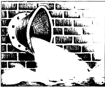
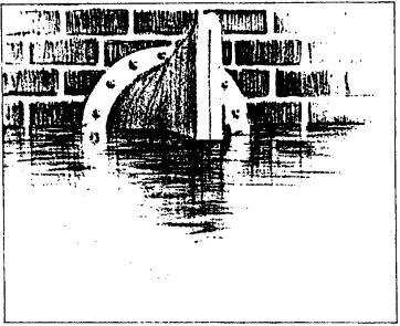
Figure 4-15. Diaphragm Check Valve Incorporating Flattened Rubber Sleeve Closure Member, Used as Tide Gate.
The check valve shown in Figure 4-13 uses a closure member in the form of a pleated annular rubber diaphragm. When the valve is closed, a lip of the diaphragm rests with the pleats closed against a core in the flow passage. Forward flow opens the pleats, and the lip retracts from the seat. Because the diaphragm is elastically strained in the open position, and travel of the lip from the fully open to the closed position is short, the diaphragm check valve closes extremely fast. This valve is well-suited for applications in which the flow varies within wide limits. However, the pressure differential for which the valve may be used is limited to 10 bar (145 lb/in2 ), and the operating temperature is limited to about 74℃ (158℉).
The closure member of the diaphragm check valve shown in Figure 4-14 consists of a fexible sleeve that is flattened at one end. The flattened end of the sleeve opens on forward flow andrecloses against reverse flow.
The sleeve is made in a large variety of elastomers, and is externally reinforced with plies of nylon fabric similar in construction to an automo- bile tire. The inside of the sleeve is soft and capable of embedding trapped solids. The valve is therefore particularly suitable for services in which the fluid carries solids in suspension or consists of a slurry.
Figure 4-15 shows an interesting application of this check valve as a tidal gate.
The valve is available in sizes as small as DN 3 (NPS 1/8) and as large as DN 3000 (NPS 120) for tidal gates.
Dashpots
The purpose of dashpots is to dampen the movement of the closure member.
The most important application of dashpots is in systems in which flow reverses very fast. If the check valve is unable to close fast enough to prevent a substantial reverse-flow buildup before sudden closure, a dash- pot, designed to come into play during the last closing movements, can considerably reduce the formation of surge pressure.
