Resistance Coefficient For Valve
Valves maybe regarded as analogous to control orifices in which the area of opening is readily adjustable. As such, the friction loss across the valve varies with flow, as expressed by the general relationship

where
v = flow velocity
Δh = headloss
Δp = pressure loss
For any valve position, numerous relationships between flow and flow resistance have been established, using experimentally determined resis- tance or flow parameters. Common parameters so determined are the resistance coefficient ζ and, dependent on the system of units, the flow coefficientsCv, Kv , and Av . It is standard practice to base these parameters on the nominal valve size.17, 18
Resistance Coefficient ζ
The resistance coefficient ζ defines the friction loss attributable to a valve in a pipeline in terms of velocity head or velocity pressure, as expressed by the equations

where
ρ = density of fluid
g = local acceleration due to gravity
The equations are valid for single-phase flow of Newtonian liquids and for both turbulent and laminar flow conditions. They may also be used for flow of gas at low Mach numbers. As the Mach number at the valve inlet approaches 0.2, the effects of compressibility become noticeable but are unlikely to be significant even for Mach numbers up to 0.5.17
Valves of the same type but of different manufacture, and also of the same line but different size, are not normally geometrically similar. For this reason, the resistance coefficient of a particular size and type of valve can differ considerably between makes. Table 2-3 can therefore provide only typical resistance-coefficient values. The values apply to fully open valves only and for Re ≥ 104 . Correction factor K1 for partial valve opening may be obtained from Figure 2-4 through 2-7.
The Engineering Sciences Data Unit, London, 17 deals more com- prehensively with pressure losses in valves. Their publication also covers correction factors for Re < 104 and shows the influence of valve size on the ζ-Value and scatter of data, as obtained from both pub- lished and unpublished reports and from results obtained from various manufacturers.
In the case of partially open valves and valves with reduced seat area, as in valves with a converging/diverging flow passage, the energy of the flow stream at the vena contracta converts partially back into static energy.
Table 2-3
Approximate Resistance Coefficients of Fully Op en Valves Under
Conditions of Fully Turbulent Flow
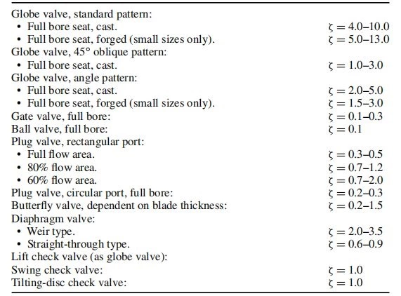
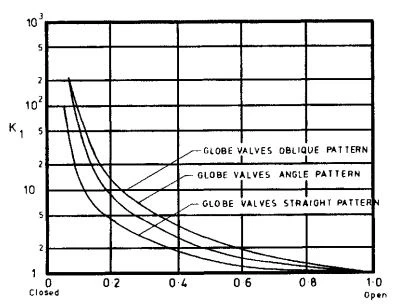
Figure 2-4. Approximate Effect of Partial Opening of Globe Valves on Resistance Coefficient.
(Courtesy of Engineering Sciences Data Unit. Reproduced from Item No. 69022, Figure 13.)
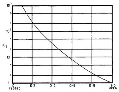
Figure 2-5. Approximate Effect of Partial Opening of Gate Valves on Resistance Coefficient.
(Courtesy of Engineering Sciences Data Unit. Reproduced from Item No. 69022, Figure 14.)
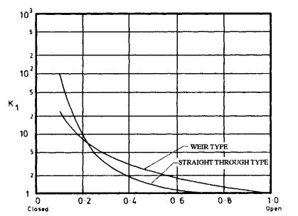
Figure 2-6. Approximate Effect of Partial Opening of Diaphragm Valves on Resistance Coefficient.
(Courtesy of Engineering Sciences Data Unit. Reproduced from Item No. 69022, Figure 15.)
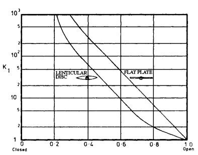
Figure 2-7. Approximate Effect of Partial Opening of Butterfly Valves on Resistance Coefficient.
(Courtesy of Engineering Sciences Data Unit. Reproduced from Item No. 69022, Figure 12.)
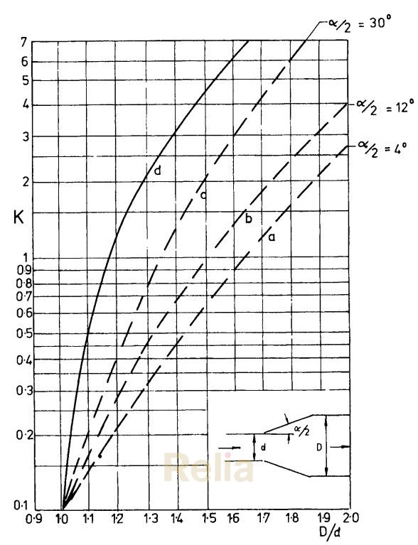
Figure 2-8. Resistance Coefficient of Fully Open Gate Valves with Converging Diverging Flow Passage and Eye Piece Between the Seats. Curves a to c Apply to L ≥ 12 D, and Curve d for L = Zero, Where L = Straight Length of Pipe Downstream of Venturi Throat. (Courtesy of VDl Verlag GmbH, Reproduced from BWKArbeitsblatt 42, Dec. 1953, by H. HaferkampandA. Kreuz.)
Figure 2-8 shows the influence of the pressure recovery on the resistance coefficient of fully open venturi-type gate valves in which the gap between the seats is bridged by an eyepiece.
The amount of static energy recovered depends on the ratio of the dia- meters of the flow passage (d2/D2), the taper angle (α/2) of the diffuser, and the length (L) of straight pipe after the valve throat in terms of pipe diameter (d = valve throat diameters, and D = pipe diameter).
If the straight length of pipe after the valve throat ≥ 12 D, the pressure loss cannot exceed the Borda-Carnot loss, which is:
where

vd = flow velocity in valve throat
vD = flow velocity in pipeline
This maximum pressure loss occurs if the taper angle (α/2) of the diffuser >30◦ . With a decreasing taper angle, the pressure loss decreases and reaches its lowest value at a taper angle of 4◦ .
If the straight pipe after the valve throat < 12 D, the pressure loss increases and reaches its maximum value when the static energy converted into kinetic energy gets completely lost, in which case:

The friction loss approaches this maximum value if the valve with a converging/diverging flow passage is mounted directly against a header.
