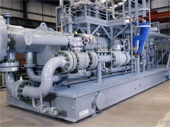
Butterfly Valves
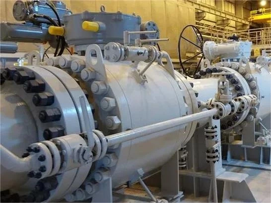
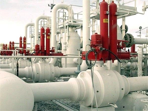
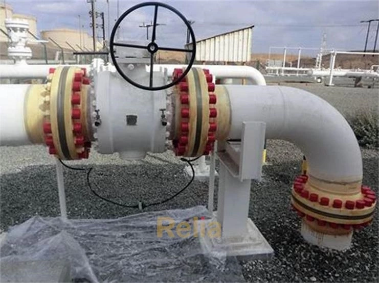
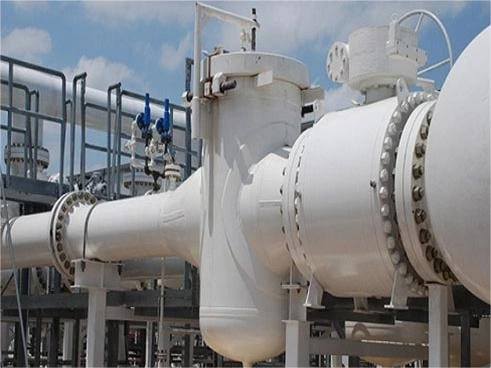
Butterfly valves are rotary valves in which a disc-shaped closure member is rotated through 90°, or approximately, to open or close the flow passage. The butterfly valves shown in Figures 3-69 through 3-83 represent a cross-section of the many variations available.
The original butterfly valve is a simple pipeline damper that is not intended for tight shut-off. This valve is still an important member of the butterfly valve family.
The advent of elastomers has initiated the rapid development of tight shut-off butterfly valves in which the elastomer serves as the sealing element between the rim of the disc and the valve body. The original use of these valves was for water.
As more chemical-resistant elastomers became available, the use of buttery valves spread to wide areas of the process industries. The elastomers used for these purposes must not only be corrosion-resistant but also abrasion-resistant, stable in size, and resiliency-retentive; that is, they must not harden. If one of these properties is missing, the elastomer may be unsuitable. Valve manufacturers can advise on the selection and limitations of elastomers for a given application.
Efforts to overcome some of the limitations of elastomers led to the development of buttery valves with PTFE seats. Other efforts led to the development of tight shut-off butterfly valves with metal seatings. With these developments, butterfly valves became available for a wide range of pressures and temperatures, based on a variety of sealing principles.
Butterfly valves give little resistance to flow when fully open and sensitive flow control when open between about 15° and 70°. Severe throttling of liquids may, of course, lead to cavitation, depending on the vapor pressure of the liquid and the downstream pressure. Any tendency of the liquid to cavitate as a result of throttling may be combated partly by sizing the butterfly valve smaller than the pipeline so that throttling occurs in the near half-open position and/or by letting the pressure drop occur in steps, using several valves, as discussed in Chapter 2. Also, if the butterfly valve is closed too fast in liquid service, the water hammer may become excessive.
By closing the butterfly valve slowly, excessive water hammer can be avoided, as discussed in Chapter 2.
Because the disc of butterfly valves moves into the seat with a wiping motion, most butterfly valves are capable of handling fluids with solids in suspension and, depending on the robustness of the seating, powders, and granules. In horizontal pipelines, butterfly valves should be mounted with the stem in the horizontal. Furthermore, when opening the valve, the bottom of the disc should lift away from solids that may have accumulated on the upstream side of the disc.
Seating Designs
From the point of seat tightness, butterfly valves may be divided into nominal-leakage valves, low-leakage valves, and tight shut-off valves. The nominal- and low-leakage valves are used mainly for throttling or flow control duty, while tight shut-off butterfly valves may be used for tight shut-off, throttling, or flow control duty.
The butterfly valves shown in Figure 3-69 are examples of nominal- and low-leakage butterfly valves in which both the seat and disc are metallic. For applications in which a lower leakage rate is required, butterfly valves that have a piston ring on the rim of the disc are available.
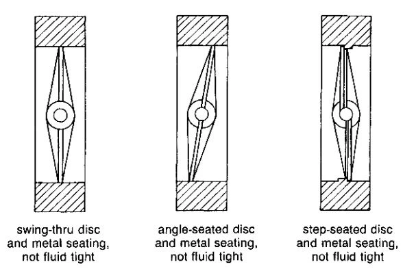
Figure 3-69. Butterfly Valves. (Courtesy of GEC-Elliot Control Valves Limited.)
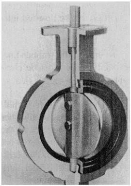
Figure 3-70. Butterfly Valve with Resilient Replaceable Liner and Interference-Seated Disc. (Courtesy of Keystone International, Inc.)
The intimate contact between the seatings of tight shut-off butterfly valves may be achieved by various means. Some of the ones more frequently used are:
1. By interference seating, which requires the disc to be jammed into the seat.
2. By forcing the disc against the seat and requiring the disc to tilt about a double offset hinge in a manner comparable to tilting disc check valves, as described on page 154.
3. By pressure-energized sealing using sealing elements such as O-rings, lip seals, diaphragms, and infatable hoses.
The majority of butterfly valves are of the interference-seated type, in which the seat has a rubber liner, as in the valves shown in Figures 3-70 through 3-72. Where rubber is incompatible with the fluid to be sealed, the liner may be made of PTFE, which is backed up by an elastomer cushion to impart resiliency to the seat.
There are several rubber liner constructions in common use. Typical constructions are:
1. A rubber liner consisting of a U-shaped ring that is slipped over the body without bonding, as in the valve shown in Figure 3-70. Such seats are readily replaceable. If the liner is made of a relatively rigid
material such as PTFE, the valve body is split along the centerline as shown in Figure 3-72 to permit the liner to be inserted without manipulation.
2. a rubber liner that is bonded to the valve body. This construction minimizes the wearing effects of rubber bunching from disc rotation that may occur if the liner is loose. On the debit side, the rubber liner cannot be replaced.
3. U-shaped rubber liner that is bonded to a metal band. This combination can be inserted into a split valve body, as in the valve shown in Figure 3-72.
To ensure that rubber-lined butterfly valves achieve their full sealing capacity, they must be correctly installed. Two requirements must be observed:
1. The rubber liner should be fully supported by the pipe flanges. The pipe flanges should therefore be of the weld-neck type rather than the slip-on type. In the case of slip-on flanges, the rubber liner remains unsupported between the valve bore and the outside diameter of the pipe. This lack of support for the liner tends to promote distortion of the liner during valve operation, resulting in early wear and seat leakage.
2. When installing the valve, the disc must initially be put into the near-closed position to protect the rim of the disc from damage during handling. Before tightening the flange bolts, the disc must be rotated into the fully open position to permit the liner to find its undisturbed position.
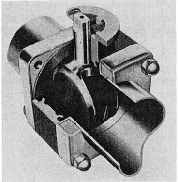
Figure 3-71. Butterfly Valve with Resilient Liner and Interference-Seated Double Disc for Double Block and Bleed. Used for Isolating Food Stuffs from Cleaning-in-Place Cleaning Fluids. (Courtesy of Amri SA.)
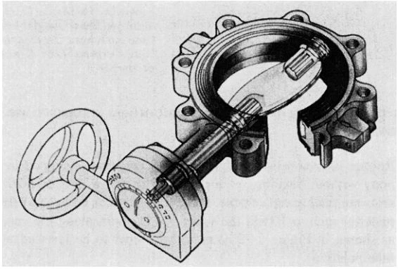
Figure 3-72. Butterfly Valve with Resilient Replaceable Liner and Interference-Seated Disc, Liner Bonded to Steel Band, Valve Body Split in Two Halves. (Courtesy of DeZurik.)
Figure 3-73 illustrates the precautions that must be taken when installing rubber-lined butterfly valves.
The flange of the rubber liner also serves as a sealing element against the pipeline flanges. The installation of additional rubber gaskets between pipe fittings and valves would tend to reduce the support of the rubber liner and, consequently, reduce the sealing capacity of the valve.
The scrap view shown in Figure 3-74 belongs to an interference-seated butterfly valve that carries the sealing element on the rim of the disc. The sealing element consists, in this case, of a heavy-section O-ring with a tail clamped to the disc. By adjusting the clamping force, the seating interference can be adjusted within limits. Because the sealing element deforms against a wide face instead of around the narrow face of a disc, the seat and unseating torques are correspondingly lower. This particular type of valve is made in larger sizes only and is used for relatively high fluid pressures.
The butterfly valves shown in Figures 3-75 and 3-76 rely on a seat seal on pressure-energized rubber elements.
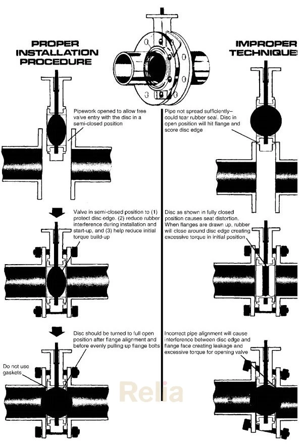
Figure 3-73. Proper and Improper Installation Procedures for Interference-Seated Butterfly Valves with Replaceable Rubber Liner. (Courtesy of Keystone International, Inc.)
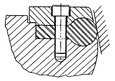
Figure 3-74. Scrap View of Interference-Seated Butterfly Valve Showing the Resilient Sealing Element Carried on the Rim of the Disc. (Courtesy of Boving & Co., Limited.)
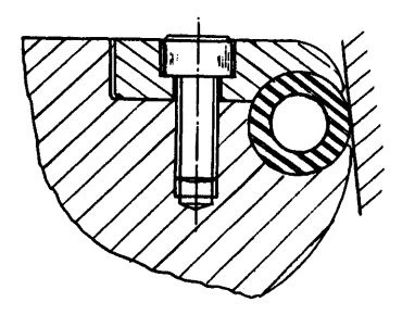
Figure 3-75. Scrap view of a butterfly valve showing an Inflatable Sealing Element Carried on the Rim of the Disc. (Courtesy of Boving & Co., Limited.)
The sealing element of the seating arrangement shown in Figure 3-75 consists of an inflatable hose mounted on the rim of the disc. The hose is reinforced inside by a metallic conduit and connected through the operating shaft to the upstream system or an external fluid pressure system. The disc is moved into the tapered seat with the hose deflated so that the seating torque is minimal. The hose is then pressurized to provide a fluid-tight seal against the seat. If the seal requires further tightening, the hose may be pumped up using a hand pump. When the valve is to be opened, the hose is first deflated so that the valve opens with a minimum of unseating torque. The valve is made to the largest size in use.
The sealing element of the butterfly valve shown in Figure 3-76 consists of a tubular-shaped diaphragm of T-cross section, which is mounted in a slot of the valve body and sealed against the flow passage. The diaphragm is pressurized on closing against the rim of the disc and depressurized on opening, like the valve shown in Figure 3-75.
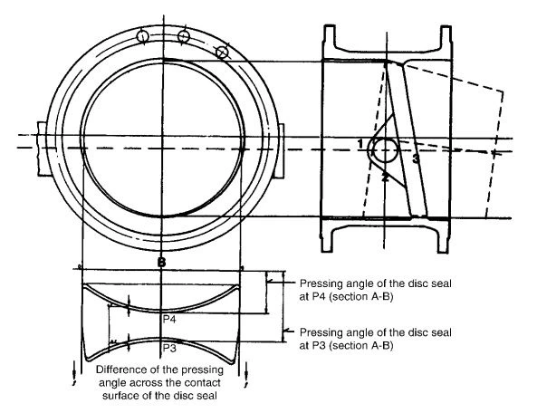
Figure 3-76. Butterfly Valve with Inflatable Sealing Element Carried in a Recess of the Valve Body. (Courtesy of GEC-Elliot Control Valves, Limited.)
Efforts to adapt butterfly valves to wider temperature and pressure ranges have led to the development of a family of butterfly valves that may be fitted with seatings of a variety of construction materials to meet operational requirements. Such seatings may be metal-to-polymer or metal-to-metal and may be designed to satisfy the requirements of fire-tested valves. The majority of these valves may be used for flow in both directions.
Valves of this performance class have acquired the name high-performance butterfly valves. The name is taken to mean that this type of butterfly valve has a greater pressure-temperature envelope than the common elastomer-lined or seated butterfly valves. Figure 3-77 through Figure 3-83 show examples of such valves. However, the illustrations do not show all the seal variations available for each particular valve.
Figure 3-77 illustrates a high-performance butterfly valve in which the seat seal is achieved by forcing the disc against the seat about a double offset hinge in a manner comparable to tilting disc check valves. The shape of the disc represents a slice from a tapered plug made at an oblique angle to the plug axis. The seating faces formed in this way are tapered on an elliptical circumference. The disc rotates around a point below the centerline of the valve and behind the seat face so that it drops into and lifts out of the seat with a little rubbing action. In this concept, the seating load is provided by the applied closing torque from the valve operator and the hydrostatic torque from the fluid pressure acting on the unbalanced area of the disc. The valve may be provided with metal-to-metal seating as illustrated, or the disc may be provided with a variety of soft sealing elements that seal against the metal seat provided by the body. With this choice of seating construction, the valve may be used for differential pressures up to 35 bar operating temperatures between −200。C ( −350。F) .
The concept of the high-performance butterfly valve shown in Figure 3-78 may be likened to that of a ball valve that uses a wafer section. The illustrated seat consists of a U-shaped plastic seal ring that is mounted in a T-slot of the valve body and backed up by an elastomeric O-ring. The O-ring imparts some initial compression stress to the seat. As the disc moves into the seat with slight interference, fluid pressure acting on the O-ring forces the seat ring into closer contact with the rim of the disc.
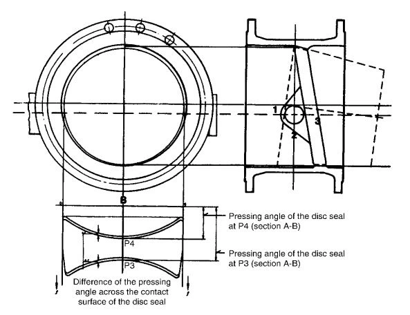
Figure 3-77. Metal-Seated High-Performance Butterfly Valve with Tapered Seating Faces and Sealing of the Disc at a Non-Interlocking Angle. (Courtesy of Clow Corporation.)
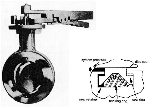
Figure 3-78. High-Performance Butterfly Valve with O-Ring-Backed Plastic Seat. (Courtesy of Posi-Seal International, Inc.)
The valve is made with a variety of seat ring constructions, including metal construction, to suit a variety of operating conditions.
The concept of the high-performance butterfly valve shown in Figure 3-79 is also borrowed from the ball valve, but with a difference from the valve shown in Figure 3-78 in that the axis of the disc is offset not only from the plane of the seat but also by a small amount from the centerline of the valve. In this way, the disc moves into the seat in a camming action, thereby moving progressively into intimate contact with the seat. Conversely, the seatings rapidly disengage during opening so that there is minimal rubbing between the seatings. The seat, as illustrated, consists of a PTFE lip seal with a tail, which is clamped between the valve body and a retainer. Once the disc has entered the seat with slight interference, fluid pressure forces the lip of the seat into more intimate contact with the rim of the disc, irrespective of whether the seat is located on the upstream or downstream side of the disc. This ability of the seatings to seal in both directions is aided by a small but controlled amount of axial movement of the disc. The valve is also available with metal and fire-tested seat constructions.
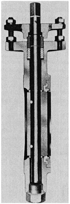
Figure 3-79. High-Performance Butterfly Valve with Flexible PTFE Lip Seat. (Courtesy of Jamesbury International Corp.)
The principle of the double offset location of the disc axis in combination with pressure-energized sealing in both directions applies also to the high-performance butterfly valves shown in Figure 3-80 through Figure 3-82. The high-performance butterfly valve shown in Figure 3-80 contains, like the valve shown in Figure 3-79, a PTFE lip seal for the seat, but of a modified shape in which the lip is supported by a titanium ring. The seat is also available in metal and fire-tested construction.
The high-performance butterfly valve shown in Figure 3-81 uses an elastomeric O-ring for the seat that is encapsulated in PTFE and anchored in the valve body. The O-ring imparts elasticity and resiliency to the seat while the PTFE envelope protects the O-ring from the effects of the system fluid.
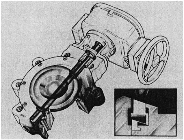
Figure 3-80. High-Performance Butterfly Valve with PTFE Lip Seal Supported by Titanium Metal Ring. (Courtesy of DeZurik.)
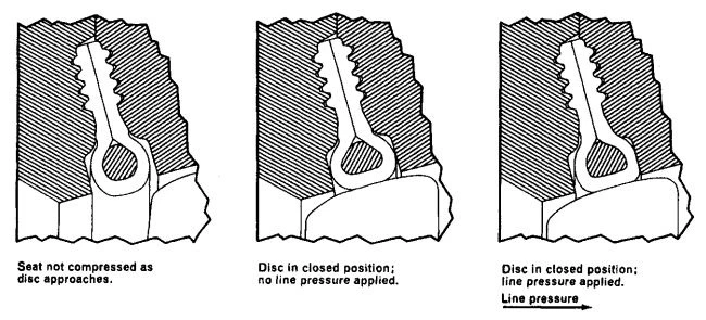
Figure 3-81. Scrap View of High-Performance Butterfly Valve Showing PTFE Encapsulated Elastomeric O-Ring Seat. (Courtesy of Bray Valve and Controls.)
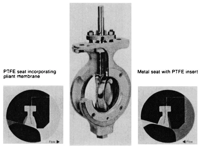
Figure 3-82. High-Performance Butterfly Valve. (Courtesy of Xomox Corporation.)
The seat is also available in fire-tested construction. The high-performance butterfly valve shown in Figure 3-82 incorporates a seat that is combined with a flexible membrane designed to return the seat to its original position each time the valve has been operated. One seat version consists of a T-shaped PTFE member that embeds a pliant membrane. A second fire-tested version consists of a U-shaped metal member with a PTFE insert that is carried on a metal membrane. The PTFE insert provides the seat seal under normal operating conditions. If the PTFE insert is destroyed in a fire, the metal seat takes over the sealing function.
The high-performance butterfly valve shown in Figure 3-83 differs from the previously described high-performance butterfly valve in that it relies on interference seating for seat tightness, using a double offset disc. The seat is available either in plastic, elastomer, metal, or plastic-metal-tested construction to suit the duty for which the valve is to be used. The performance of the plastic and metal seats relies on a backup wire winding that is designed to provide absolute seat rigidity when the valve is closed but to avoid imposing a load on the seat when the valve is open, thereby permitting the seal element to flex radially. The rigidity in the closed position is required to achieve the desired seat interference for a tight shut-off against high and low pressures, including vacuum.
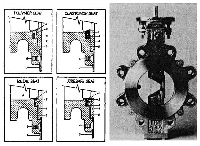
Figure 3-83. High-Performance Butterfly Valve Designed for Interference Seating. Scrap Views Show Plastic Seat, Elastomer Seat, Metal Seat, and Plastic/Metal Composition Seat for Flammable Liquid Service. (Courtesy of Keystone International, Inc.)
Butterfly Valves for Fire Exposure
Butterfly valves, which may be exposed to plant fire when handling flammable fluids, must remain essentially fluid-tight internally and externally and be operable during and after a fire. These conditions may be met by fire-tested versions of high-performance butterfly valves.
The requirements for testing and evaluating the performance of butterfly valves when exposed to fire are similar to those for ball valves, described on page 108.
Body Configurations
The preferred body configuration for butterfly valves is the wafer, which is clamped between two pipeline flanges. An important advantage of this construction is that the bolts pulling the mating flanges together carry all the tensile stresses induced by the line strains and put the wafer in compression. This compressive stress is eased by the tensile stresses imposed by the internal fluid pressure. Flanged bodies, on the other hand, have to carry all the tensile stresses imposed by the line strains, and the tensile stresses from the line pressure are cumulative. This fact, together with the ability of most metals to handle compressive loads of up to twice their limit for tensile loads, strongly recommends the use of the wafer body.
However, if the downstream side of the butterfly valve serves also as a point of disconnection while the upstream side is still under pressure, the cross-bolted wafer body is unsuitable unless provided with a false flange. A flanged body or a lugged wafer body in which the lugs are threaded at each end to receive screws from the adjacent flanges is commonly used.
Torque Characteristics of Butterfly Valves
The torque required to operate butterfly valves consists of three main components:
Th = hydrodynamic torque that is created by the flowing fluid acting on the disc.
Tb = torque to overcome bearing friction
Ts = torque required to seat or unseat the disc
The hydrodynamic torque varies with the valve opening position and the pressure drop across the valve. In the case of symmetrical discs, this torque is identical for either direction of flow, and its direction of action is against the opening motion throughout. If the disc is offset, as in the disc shown in Figure 3-84, the hydrodynamic torque differs for each direction of flow, and the lowest torque develops when the flow is toward the disc. With flow toward the shaft, the torque acts against the opening motion throughout. However, with flow toward the disc, the torque acts only initially against the opening motion and then, with further valve opening, changes its direction.
The bearing, seating, and unseating torques, on the other hand, always act against the operating motion. The magnitude of the bearing torque corresponds to the resultant hydrodynamic force on the disc, while the magnitude of the seating and unseating torques is independent of flow.
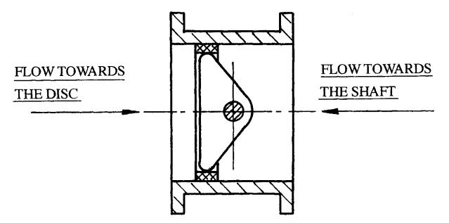
Figure 3-84. Offset Disc Configuration in Butterfly Valves.
In the case of interference-seated butterfly valves of sizes up to DN 400 (NPS 16), the seating and unseating torques normally dominate, provided the flow velocity is not too high. It is sufficient in this case to size the operating gear for these torques. However, the magnitude of the seating and unseating torques is influenced by the type of fluid handled and the operating frequency. For example, if the fluid has good lubricity and the valve is operated frequently, the seating and unseating torques are lower than for fluids that have little lubricity or consist of solids, or when the valve is operated infrequently. Manufacturers supply tables that give seating and unseating torques for various conditions of operation.
In the case of interference-seated butterfly valves above DN 400 (NPS 16) and conditions of high flow velocities, the hydrodynamic and bearing torques can greatly exceed the seating and unseating torques. The operator for such valves may therefore have to be selected in consultation with the manufacturer.
Figure 3-85 shows typical opening torque characteristics of butterfly valves with symmetrical and offset discs, representing the summary of torques at a constant pressure loss across the valve. Under most operating conditions, however, the pressure drop across the valve decreases as the valve is opened, as shown, for example, in Figure 3-86, for a given pumping installation. The decreasing pressure drop, in turn, decreases the corresponding operating torque as the valve opens. The maximum operating torque shifts thereby from the region of the fully open valve to the region of the partially open valve, as shown in Figure 3-87. This torque is lowest if the disc is of the offset type and the direction of flow is toward the disc. However, this advantage is obtained at the cost of a somewhat higher pressure drop. If the valve is large and the flow velocity is high, this torque characteristic can be exploited to lower the cost to the operator.
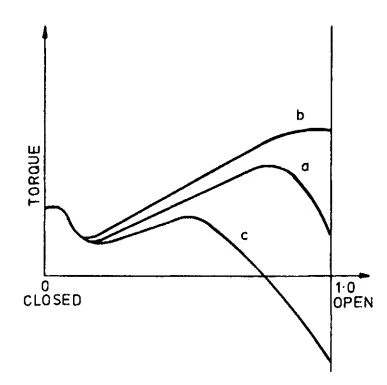
Figure 3-85. Opening Torque Characteristics of Butterfly Valves at Constant Pressure Drop Across Valve. (Reprinted from Schiff and Hafen, 40 Courtesy of VAG-Armaturen GmbH.)
Curve a: Symmetrical Disc, Flow From Either Direction
Curve b: Off-Set Disc, Flow Towards Shaft
Curve c: Off-Set Disc, Flow
Towards Disc
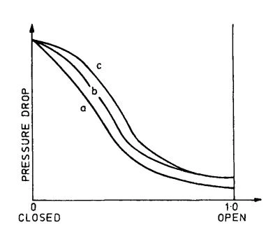
Figure 3-86. Pressure Drop Across Butterfly Valves for All Opening Positions in Actual Pumping Installation. (Reprinted from Schiff and Hafen, 40 Courtesy of VAG-Armaturen GmbH.)
Curve a: Symmetrical Disc, Flow From Either Direction
Curve b: Off-Set Disc, Flow Towards Shaft
Curve c: Off-Set Disc, Flow Towards Disc
Standards on Butterfly Valves
Appendix C provides a list of U.S. and British standards on butterfly valves.
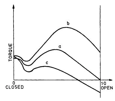
Figure 3-87. Opening Torque Characteristics of Butterfly Valves in the Actual Pumping Installation. (Reprinted from Schiff and Hafen, 40 Courtesy of VAG-Armaturen GmbH.)
Curve a: Symmetrical Disc, Flow From Either Direction
Curve b: Off-Set Disc, Flow Towards Shaft
Curve c: Off-Set Disc, Flow Towards Disk
Applications
Duty:
- Stopping and starting flow
- Controlling flow
Service:
- Gases
- Liquids
- Slurries
- Powder
- Granules
- Sanitary handling of pharmaceuticals and food stuffs
- Vacuum
