Diaphragm Valves
Diaphragm valves are flex-body valves in which the valve body consists of a rigid and flexible section. The flexible body section is provided by a diaphragm, which, in connection with a compressor, represents the closure member. The rigid body section provides the seat and may consist of a weir across the flow passage, as in the valve shown in Figure 3-93, or be provided by the wall of a straight-through flow passage, as in Figure 3-94.
Diaphragm valves share a similar advantage with pinch valves: a flow passage that is not obstructed by moving parts and is free of crevices. Therefore, they may be used similarly to pinch valves, including the sanitary handling of foodstuffs and pharmaceuticals.
Weir-Type Diaphragm Valves
The weir in the flow passage is designed to reduce the flexing of the diaphragm to a minimum while still providing a smooth and streamlined flow passage. Therefore, the flexing stress in the diaphragm is minimal, resulting in a correspondingly long diaphragm life. The short stroke of these valves also permits the use of plastics such as PTFE for the diaphragm, which would be too inflexible for longer strokes. The back of such diaphragms is lined with an elastomer, which promotes uniform seating stress upon valve closing.
Weir-type diaphragm valves may also be used in general and high vacuum service. However, some valve makers require a specially reinforced diaphragm in high vacuum service.
Because the diaphragm area is enormous compared with the flow passage, the fluid pressure imposes a correspondingly high force on the raised diaphragm. The resulting closure torque limits the size to which diaphragm valves can be made. Weir-type diaphragm valves shown in Figure 3-93 are typically made in sizes up to DN 350 (NPS 14). Larger weir-type diaphragm valves up to DN 500 (NPS 20) are provided with a double-bonnet assembly, as shown in Figure 3-95.
Weir-type diaphragm valves are also available with a body of T-configuration, as shown in Figure 3-96, in which a branch connects to the central flow passage without impeding pipeline flow. These valves' primary function is sampling duty, where the taking of an actual sample from the flowing fluid must be assured.
The valve's stem shown in Figure 3-93 is of the rising type to protect the external stem thread from dust and immediate outside corrosive influences. The handwheel carries a shroud that covers the stem thread while sliding over a yellow lift indicator sleeve. The yellow lift-indicator sleeve, in turn, carries a prepacked lubrication chamber to lubricate the stem thread for a long life.
If required, the stem may be provided with an O-ring seal against the bonnet to prevent fluid from escaping into the surroundings of the valve should the diaphragm break in service.
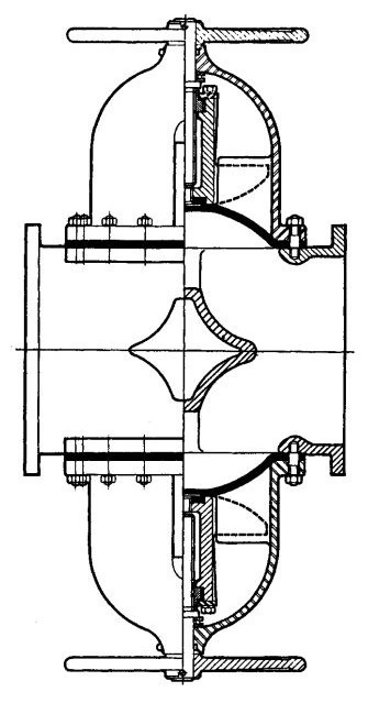
Figure 3-95. Diaphragm Valve, Weir Type, with Double-Bonnet Assembly in Connection with Large Valve Sizes. (Courtesy of Saunders Valve Company Limited.)
Conventional weir-type diaphragm valves may also be used in horizontal lines that must be self-draining. Self-draining is achieved by mounting the valve with the stem approximately 15° to 25° up from the horizontal, provided the horizontal line has some fall.
Straight-Through Diaphragm Valves
Diaphragm valves with a straight-through flow passage require a more flexible diaphragm than weir-type diaphragm valves. For this reason, the construction material for diaphragms of straight-through diaphragm valves is restricted to elastomers.
Because of these diaphragms' high flexibility and significant area, high vacuum will tend to balloon the diaphragm into the flow passage.
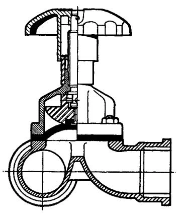
Figure 3-96. Diaphragm Valve, Weir Type, with T-Branch. (Courtesy of Saunders Valve Company Limited.)
The degree of ballooning varies with the make, causing only a slight and acceptable reduction in flow area or a collapse of the diaphragm. In the latter case, the bonnet must be evacuated to balance the pressures on the diaphragm. When using these valves for high vacuum, the manufacturer should be consulted.
Straight-through diaphragm valves are also available with full-bore and reduced-bore flow passage. In the case of reduced-bore valves, the bonnet assembly of the next smaller valve is used. For example, a DN 50 (NPS 2) reduced-bore valve is fitted with a DN 40 (NPS 11) bonnet. The construction of the bonnet is otherwise similar to that of weir-type diaphragm valves.
The size range of straight-through diaphragm valves typically covers valves up to DN 350 (NPS 14).
Construction Materials
The valve body of diaphragm valves is available in various construction materials, including plastics, to meet service requirements. The simple body shape also lends itself to lining with many corrosion-resistant materials, often leading to low-cost solutions for an otherwise expensive valve.
Because the diaphragm separates the bonnet from the flowing fluid, the bonnet is usually made of cast iron and epoxy coated inside and outside. If requested, the bonnet is also available in various other materials.
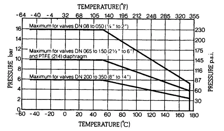
Figure 3-97. Pressure/Temperature Relationship of Weir-Type Diaphragm Valves. (Courtesy of Saunders Valve Company Limited.)
Diaphragms are available in a great variety of elastomers and plastics. Valve manufacturers' catalogs advise the user on selecting the diaphragm material for a given application.
Valve Pressure/Temperature Relationships
Figures 3-97 and 3-98 show typical pressure/temperature relationships of weir-type and straight-through diaphragm valves. However, not all construction materials permit the full range of these relationships. The valve user must, therefore, consult the manufacturer's catalog for the permissible operating pressure at a given operating temperature.
Valve Flow Characteristics
Figure 3-99 shows the typical inherent and installed flow characteristics of weir-type diaphragm valves, though the shapes of the curves may vary to some extent between valve sizes. In the case of automatic control, these characteristics may be modified using a variable cam positioner.
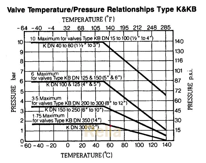
Figure 3-98. Pressure/Temperature Relationship of Straight-Through Diaphragm Valves. (Courtesy of Saunders Valve Company Limited.)
Operational Limitations
Like pinch valves, diaphragm valves displace a certain amount of fluid when operated; diaphragm valves are positive-displacement type valves. For this reason, diaphragm valves must not be installed as shut-off valves in lines containing an incompressible fluid where the fluid has no room to move.
Standards On Diaphragm Valves
Appendix C lists U.S., British and ISO standards on diaphragm valves.
Applications
- Duty for weir-type and straight-through diaphragm valves:
- Stopping and starting flow
- Controlling flow
- Service for weir-type diaphragm valves:
- Gases may carry solids
- Liquids may carry solids
- Viscous fluids
- Leak-proof handling of hazardous fluids
- Sanitary handling of pharmaceuticals and foodstuffs
- Vacuum
- Service for straight-through diaphragm valves:
- Gases may carry solids
- Liquid may carry solids
- Viscous fluids
- Sludges
- Slurries may carry abrasives
- Dry media
- Vacuum (consult manufacturer)
