Piston Valves
Piston valves are closing-down valves in which a piston-shaped closure member intrudes into or withdraws from the seat bore, as in the valves shown in Figure 3-20 through Figure 3-24.
In these valves, the seat seal is achieved between the lateral faces of the piston and the seat bore. When the valve is being opened, flow cannot start until the piston has been completely withdrawn from the seat bore. Any erosive damage occurs, therefore, away from the seating surfaces. When the valve is closed, the piston tends to wipe away any solids that might have deposited themselves on the seat. Piston valves may thus handle fluids that carry solids in suspension. When some damage occurs to the seatings, the piston and the seat can be replaced insitu, and the valve is like new without any machining.
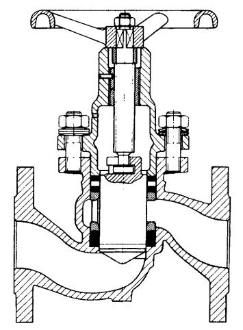
Figure 3-20. Piston Valve, Standard Pattern, Seat Packing Mounted in Valve Body, Piston Pressure Unbalanced.
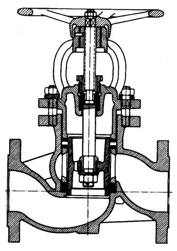
Figure 3-21. Piston Valve, Standard Pattern, Seat Packing Mounted in Valve Body, Piston Pressure Balanced.
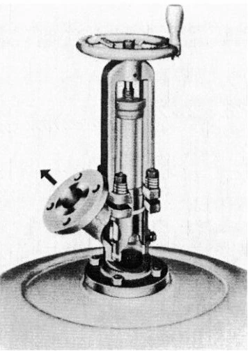
Figure 3-22. Piston Valve, Adapted for Draining Vessels, Seat Packing Mounted in Valve Body.
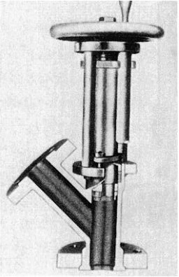
Figure 3-23. Piston Valve Adapted for Draining Vessels; Seat Packing Mounted on Piston; the “Ram-Seal” Principle. (Courtesy of Fetterolf Corporation.)
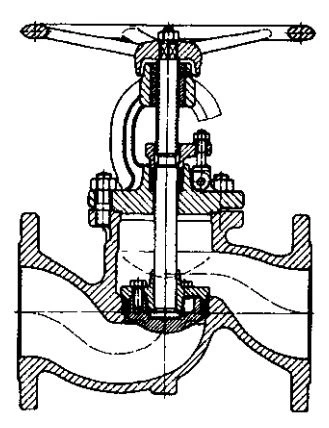
Figure 3-24. Piston Valve, Standard Pattern, Seat Packing Mounted on Piston. (Courtesy of Rich. Klinger AG.)
Like globe valves, piston valves permit good flow control. If sensitive flow adjustment is required, the piston may be fitted with a needle-shaped extension. Piston valves are also used for stopping and starting flow when flow resistance due to the tortuous flow passage is accepted.
Construction
The seatings of piston valves are formed by the lateral faces of the valve bore and the piston. A fluid-tight contact between these faces is achieved by a packing that either forms part of the valve bore, as in the valves shown in Figure 3-20 through Figure 3-22, or part of the piston, as in the valves shown in Figure 3-23 and Figure 3-24. Packings commonly used for this purpose are compression packings based on compressed asbestos, or PTFE, and O-ring packings.
In the case of the piston valve shown in Figure 3-20, the piston moves in two packings that are separated by a lantern ring. The lower packing represents the seat packing, while the upper packing seals the piston to the atmosphere. The bonnet serves thereby as the gland that permits both packings to be tightened through the tightening of the cover bolts. Disc springs under the nuts of the cover bolts minimize variations in packing stress due to thermal contraction and expansion of the valve parts. When one of the packings leaks, the fluid seal can be restored by retightening the bolts. Retightening must be carried out while the valve is closed to prevent an unrestrained expansion of the seat packing into the valve bore.
The valve shown in Figure 3-21 differs from the one in Figure 3-20 only in that the piston is pressure-balanced. The two packings around the piston are both seat packings, and a separate packing is provided for the stem. The purpose of balancing the piston is to minimize the operating effort in large valves operating against high fluid pressures.
The packing train of the valve shown in Figure 3-22 is likewise stressed through the bonnet in conjunction with springs under the nuts of the cover bolts, or with a spring between the bonnet and the packing. However, as the piston moves into the final closing position, a shoulder on the piston contacts a compression ring on top of the packing so that any further progression of the piston tightens the packing still further.
The piston valve shown in Figure 3-23 carries the seat packing on the end of the piston instead of in the valve bore. The packing is supported thereby on its underside by a loose compression ring. When the piston moves into the final closing position, the compression ring comes to rest on a shoulder in the seat bore, so that any further progression of the piston causes the compression ring to tighten the packing. Because the packing establishes interference with the seat in the last closing stages only, the operating effort of the valve is lower over a portion of the piston travel than that of the foregoing valves.
The piston valve shown in Figure 3-24 also carries the seat packing on the piston. However, the loose compression ring is replaced by a friction ring that acts as a spring element and, as such, pre-stresses the packing. When the piston moves into the seat, the friction ring comes to rest in the seat bore, and any progression of the piston increases the packing stress.
National standards that apply specifically to piston valves do not exist.
Applications
Duty:
- Controlling flow
- Stopping and starting the flow
Service:
- Gases
- Liquids
- Fluids with solids in suspension
- Vacuum
