Plug Valves
Plug valves are rotary valves in which a plug-shaped closure member is rotated through increments of 90° to engage or disengage a porthole or holes in the plug with the ports in the valve body. The shape of the plug may thereby be cylindrical, as in the valves shown in Figure 3-49 through Figure 3-53, or tapered, as in the valves shown in Figure 3-54 through Figure 3-58. Rotary valves with ball-shaped plugs are likewise members of the plug valve family but are conventionally referred to as ball valves. These valves are discussed separately on page 108.
The shape of the port is commonly rectangular in parallel plugs and truncated triangular in taper plugs. These shapes permit a slimmer valve construction with reduced weight, but at the expense of some pressure drop. Full-area round-bore ports are normally used only if the pipeline has to be scraped or the nature of the fluid demands a full-area round bore. However, some plug valves are made only with round-bore because of the method of sealing employed.
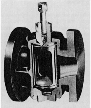
Figure 3-49. Lubricated Cylindrical Plug Valve. (Courtesy of Pegler Hattersley Limited.)
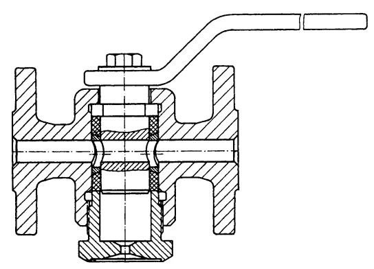
Figure 3-50. Cylindrical Plug Valve with Packing Sleeve. (Courtesy of Rich. Klinger AG.)Plug valves are best suited for stopping and starting flow and flow diversion, though they are also used occasionally for moderate throttling, depending on the nature of the service and the erosion resistance of the seating. Because the seats move against each other with a wiping motion and, in the fully open position, are also fully protected from contact with the flowing fluid, plug valves are generally capable of handling fluids with solids in suspension.
Cylindrical Plug Valves
The use to which plug valves can be put depends, to some extent, on the way the seal between the plug and the valve body is produced. In the case of cylindrical plug valves, four sealing methods are frequently employed: by a sealing compound, by expanding the plug, by O-rings, and by wedging an eccentrically shaped plug to the seat.
The cylindrical plug valve shown in Figure 3-49 is a lubricated plug valve in which the seat seal depends on the presence of a sealing compound between the plug and the valve body. The sealing compound is introduced to the seatings through the shank of the plug by a screw or an injection gun.
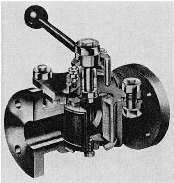
Figure 3-51. Cylindrical Plug Valve with Expandable Split Plug. (Courtesy of Langley Alloys Limited.)
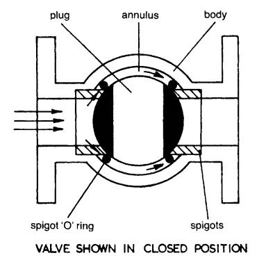
Figure 3-52. Cylindrical Plug Valve with O-Ring Seat Seal. Valve shown in closed position. (Courtesy of Orseal Limited.)
Thus, it is possible to restore a defective seat seal by injecting an additional amount of sealing compound while the valve is in service.
Because the seating surfaces are protected in the fully open position from contact with the flowing fluid and a damaged seat seal can easily be restored, lubricated plug valves have been found to be particularly suitable for abrasive fluids. However, lubricated plug valves are not intended for throttling, although they are sometimes used for this purpose. Because throttling removes the sealing compound from the exposed seating surfaces, the seat seal must be restored, in this case, each time the valve is closed.
Unfortunately, the manual maintenance of the sealing compound is often a human problem. Automatic injection can overcome this problem, but it adds to the cost of installation. When the plug has become immovable in the valve body due to lack of maintenance or improper selection of the sealing compound or because crystallization has occurred between the seatings, the valve must be cleaned or repaired.
The seat seal of the cylindrical plug valves shown in Figures 3-50 and 3-51 depends on the ability of the plug to expand against the seat. The plug of the valve shown in Figure 3-50 is fitted for this purpose with a packing sleeve, which is tightened against the seat by a follower nut.
The packing commonly consists of compressed asbestos or solid PTFE. If the packing needs retightening to restore the seat tightness, this must be carried out while the valve is in the closed position to prevent the packing from expanding into the flow passage. The valve is made only in small sizes but may be used for fairly high pressures and temperatures. Typical applications for the valve are the isolation of pressure gauges and level gauges.
The plug of the valve shown in Figure 3-51 is split into two halves and spread apart by a wedge, which may be adjusted from the outside. The seat seal is provided by narrow PTFE rings that are inserted into the faces of the plug halves. By this method of sealing and seat loading, the valve is also capable of double block and bleed.
The valve is specifically intended for duties for which stainless steel and other expensive alloys are required, and it is capable of handling slurries but not abrasive solids. Very tacky substances also tend to render the wedging mechanism inoperable. But within these limits, the valve has proven to be very reliable under conditions of frequent valve operation.
Figure 3-52 shows a parallel plug valve in which the seat seal is protected by O-rings. The O-rings are mounted on spigot-like projections of the upstream and downstream ports, which form the seats for the plug.
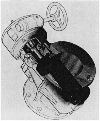
Figure 3-53. Cylindrical Plug Valve with Eccentric Semi-Plug. (Courtesy of DeZurik.)
When the valve is closed, the fluid pressure enters the cavity between the plug and the valve body past the upstream O-ring and forces the downstream O-ring into intimate contact with the plug and the projections of the valve ports. The main application of this valve is for high-pressure hydraulic systems.
Efforts to eliminate most of the friction between the seatings and to control the sealing capacity of the valve by applying torque led to the development of the eccentric plug valve shown in Figure 3-53, in which an eccentric plug matches a raised face in the valve body. This method of seating makes the valve easy to operate and capable of handling sticky substances that are difficult to handle with other types of valves. The seating faces may be in metallic contact or lined with an elastomer or plastic in conjunction with the lining of the valve body.
Taper Plug Valves
Taper plug valves permit the leakage gap between the seatings to be adjusted by forcing the plug deeper into the seat. The plug may also be rotated while in intimate contact with the valve body or lifted out of the valve body prior to rotation and seated again after being rotated through 90°, depending on the design.
Figure 3-54 shows a taper plug valve with unlubricated metal seatings. Because the friction between the seatings is high in this case, the permissible seating load is limited to keep the plug freely movable. The leakage gap between the seatings is therefore relatively wide, so the valve achieves a satisfactory seat seal only with liquids that have a high surface tension or viscosity. However, if the plug has been coated with grease prior to installation, the valve may also be used for wet gases such as wet and oily compressed air.
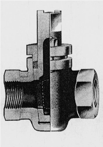
Figure 3-54. Taper Plug Valve with Unlubricated Metal Seatings. (Courtesy of Pegler Hattersley Limited.)
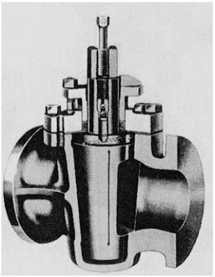
Figure 3-55. Lubricated Taper Plug Valve. (Courtesy of Serck Audco Pty. Ltd.)
The lubricated taper plug valve shown in Figure 3-55 is similar to the lubricated cylindrical plug valve, except for the shape of the plug. Both valves may also serve the same duties. However, the lubricated taper plug valve has one operational advantage. Should the plug become immovable after a prolonged static period or as a result of neglected lubrication, the injection of additional sealing compound can lift the plug off the seat just enough to allow the plug to be moved again. When freeing the plugin this way, the gland should not be slackened, as is sometimes done by users, but rather judiciously tightened. On the debit side, it is also possible to manually overtighten the plug and cause the plug to seize in this way.
The valve shown in Figure 3-56 is a lubricated taper plug valve in which the plug is mounted in the inverted position and divorced from the stem.
The plug is adjusted in its position by a screw in the valve cover while the sealant is injected into the body at the stem end. To prevent the fluid pressure from driving the plug to the seat, the plug ends are provided with balance holes that permit the fluid pressure to enter the cavities at both plug ends. By this design, the plug valve may be used for very high pressures without becoming inoperable because of the fluid pressure driving the plug to the seat.
Efforts to overcome the maintenance problem of lubricated plug valves led to the development of the taper plug valve shown in Figure 3-57, in which the plug moves in a PTFE body sleeve. The PTFE body sleeve keeps the plug from sticking, but the operating torque can still be relatively high due to the large seating area and the high seating stress. On the other hand, the large seating area provides good protection against leakage should some damage occur to the seating surface. As a result, the valve is rugged and tolerates abusive treatment. The PTFE sleeve also permits the valve to be made of exotic materials that would otherwise tend to bind in mutual contact. In addition, the valve is easily repaired in the field, and no lapping of the plug is required.
The taper plug valve shown in Figure 3-58 is designed to eliminate most of the sliding between the seatings. This is achieved by lifting the plug out of the body seat by means of a hinged level arrangement prior to it being rotated and reseating it after it is rotated to the desired position.
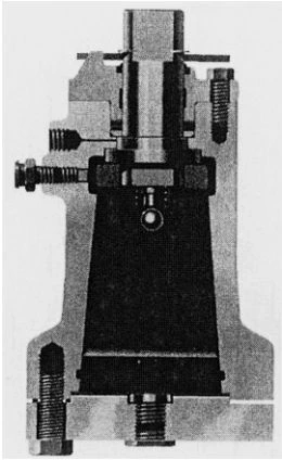
Figure 3-56. Lubricated Taper Plug Valve with Inverted Pressure-Balanced Plug. (Courtesy of Nordstrom.)
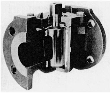
Figure 3-57. Taper Plug Valve with PTFE Body Sleeve. (Courtesy of Xomox Corporation, “Tufline.”)
The plug may be rubber-faced and is, by its taper, normally self-locking. This particular valve is a multiport companion valve to the eccentric plug valve shown in Figure 3-53.
Antistatic Device
In plug valves, seats and packings made of a polymeric material such as PTFE can electrically insulate the plug and the valve stem from the valve body. Under these conditions, friction from the flowing fluid may generate an electrostatic charge in the plug and the stem that is high enough to produce an incendiary spark. This possibility is more pronounced with two-phase flow. If the fluid handled by the valve is flammable, the valve must be provided with an antistatic device, which achieves electrical continuity between the plug, stem, and valve body.
Plug Valves for Fire Exposure
Plug valves, which may be exposed to a plant fire when handling a flammable fluid, must remain essentially fluid-tight internally and externally and be operable during and after a fire. This degree of resistance to fire damage is particularly difficult to achieve when the plug valve normally relies on polymers for seat and stem seal. Common practice in this case is to provide the valve with an auxiliary metal seat in close proximity to the plug, against which the plug can float after the soft seat has disintegrated. The soft stem packing can readily be replaced with a fire-resistant packing.
The requirements for testing and evaluating the performance of valves exposed to fire are similar to those for ball valves, described on pages 108 and 109.
Multiport Configuration
Plug valves adapt readily to multiport configurations such as those shown in Figure 3-59. The valves may be designed for transflow, in which case the second flow passage opens before the first closes, or for non-transflow, in which case the first flow passage closes before the second opens. The transflow sequence is intended for duties in which the flow cannot be momentarily interrupted. For example, on the outlet of a positive displacement pump that is not protected by a relief valve. The non-transflow sequence may be required when a momentary flow into one port from the other is not permissible, for example, at the outlet of a measuring vessel, but the plug is not normally intended to shut off fluid-tight in the intermediate position. In most practical applications, however, when valves are operated fairly quickly, there is little difference between the effects of transfow and non-transflow in flow.
The direction of flow through lubricated multiport valves should be such that the fluid pressure forces the plug against the port that is to be shut off.
If the pressure acts in the opposite direction, lubricated plug valves will not hold their rated pressure.
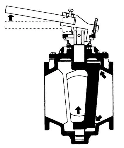
Figure 3-59. Multiport Configuration of Plug Valves. (Courtesy of Serck Audco Pty. Ltd.)
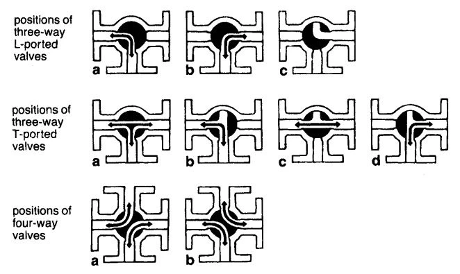
Figure 3-59. Multiport Configuration of Plug Valves. (Courtesy of Serck Audco Pty. Ltd.)
Face-to-Face Dimensions and Valve Patterns
The designers of the U.S. and British standards of cast iron and carbon steel plug valves have attempted to make the face-to-face dimensions of plug valves identical to those of gate valves. To accommodate plug valves within these dimensions, some concessions had to be made on the flow area through the plug in the lower pressure ratings. But even with these concessions, plug valves for class 150 can be made interchangeable with gate valves up to DN 300 (NPS 12) only. This limitation led to the introduction of an additional long-series plug valve for Class 150. As a result, the following valve patterns have emerged:
1. Short pattern: It has reduced-area plug ports and face-to-face dimensions that are interchangeable with gate valves. This pattern applies to sizes up to DN 300 (NPS 12) in class 150 only.
2. Regular pattern: It has plug ports with areas larger than short or venturi patterns. The face-to-face dimensions are interchangeable with gate valves for pressure ratings of Class 300 and higher. Regular pattern plug valves for class 150 have face-to-face dimensions in a long series that are not interchangeable with gate valves.
3. Venturi pattern: It has reduced area ports and body throats that are approximately venturi. The face-to-face dimensions are interchangeable with gate valves for pressure ratings of Class 300 and higher. Venturi-pattern plug valves for class 150 have face-to-face dimensions in a long series that are not interchangeable with gate valves.
4. Round-port full-area pattern: it has full-area round ports through the valve. The face-to-face dimensions are longer than short, regular, or venturi-pattern plug valves and are noninterchangeable with gate valves.
Standards Pertaining to Plug Valves
Appendix C provides a list of U.S. and British standards pertaining to plug valves.
Applications
Duty:
- Stopping and starting flow
- Moderate throttling
- Flow diversion
Fluids:
- Gases
- Liquids
- Non-abrasive slurries
- Abrasive slurries for lubricated plug valves
- Sticky fluids for eccentric and lift plug valves
- Sanitary handling of pharmaceuticals and food items
- Vacuum
