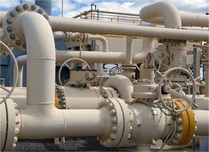
Wedge Gate Valve
Wedge gate valves differ from parallel gate valves in that the closure member is wedge-shaped instead of parallel, as shown in Figure 3-34 through Figure 3-45. The purpose of the wedge shape is to introduce a high supplementary seating load that enables metal-seated wedge gate valves to seal not only against high, but also low, fluid pressures. The degree of seat tightness that can be achieved with metal-seated wedge gate valves is there- fore potentially higher than with conventional metal-seated parallel gate valves. However, the upstream seating load is not normally high enough to permit block-and-bleed operation of metal-to-metal seated wedge gate valves.
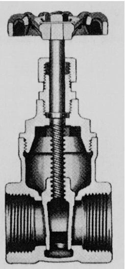
Figure 3-34. Wedge Gate Valve with Plain Hollow Wedge, Screwed-in Bonnet, and Internal Screw.
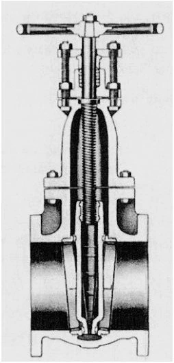
Figure 3-35. Wedge Gate Valve with Plain Hollow Wedge, Bolted Bonnet, and Internal Screw.
The bodies of these valves carry guide ribs, or slots, in which the disc travels. The main purpose of these guides is to carry the wedge away from the downstream seat except for some distance near the closed valve position so as to minimize wear between the seatings. A second purpose of the guides is to prevent the disc from rotating excessively while travel- ling between the open and closed valve positions. If some rotation occurs, the disc will initially jam on one side between the body seatings and the rotate into the correct position before travelling into the final seating position.
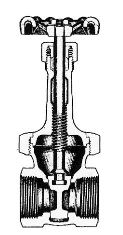
Figure 3-36. Wedge Gate Valve with Plain Solid Wedge, Union Bonnet, and Internal Screw.
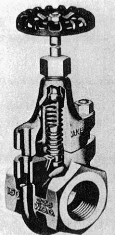
Figure 3-37. Wedge Gate Valve with Clamped Bonnet, Internal Screw.
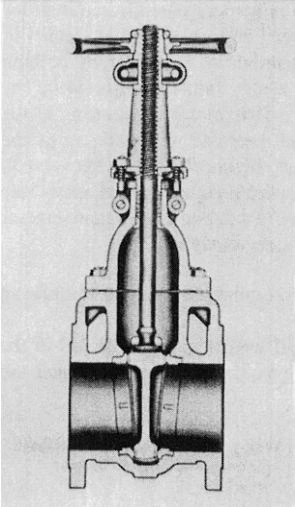
Figure 3-38. Wedge Gate with Plain Solid Wedge, Bolted Bonnet, and External Screw.
There are also types of wedge gate valves that can dispense with a wedge guide, such as the valve shown in Figure 3-45 in which the wedge is carried by the diaphragm.
Compared with parallel gate valves, wedge gate valves also have some negative features:
- Wedge gate valves cannot accommodate a follower conduit as con- veniently as parallel gate valves can.
- As the disc approaches the valve seat, there is some possibility of the seatings trapping solids carried by the fluid. However, rubber-seated wedge gate valves, as shown in Figure 3-44 and Figure 3-45, are capable of sealing around small trapped solids.
- An electrical drive for wedge gate valves is more complicated than for parallel gate valves in that the drive must be torque-limited instead of travel-limited. The operating torque of the drive must thereby be high enough to effect the wedging of the wedge into the seats while the valve is being closed against the full differential line pressure. If the valve is closed against zero differential pressure, the wedging of the wedge into the seats becomes accordingly higher. To permit the valve to be opened again against the full differential pressure, and to allow also for a possible increase of the operating effort due to thermal movements of the valve parts, the operator must be generously sized.
The limitations of wedge gate valves are otherwise similar to those of parallel gate valves. Efforts to improve the performance of wedge gate valves led to the development of a variety of wedge designs; the most common ones are described in the following section.
Variations of Wedge Design
The basic type of wedge is the plain wedge of solid or hollow construc- tion, as in the valves shown in Figure 3-34 through Figure 3-39. This design has the advantage of being simple and robust, but distortions of the valve body due to thermal and pipeline stresses may unseat or jam the metal- seated wedge. Afailure of this kind is more often experienced in valves of light-weight construction.
The sealing reliability of gate valves with a plain wedge can be improved by elastomeric or plastic sealing elements in either the seat or the wedge. Figure 3-40 shows a seat in which the sealing element is a PTFE insert. The PTFE insert stands proud of the metal face just enough to ensure a seal against the wedge.
Efforts to overcome the alignment problem of plain wedges led to the development of self-aligning wedges. Figure 3-41, Figure 3-42, and Figure 3-43 show typical examples. The simplest of these is the flexible wedge shown in Figure 3-41 and Figure 3-42, which is composed of two discs with an integral boss in between. The wedge is sufficiently flexible to find its own orientation. Because the wedge is simple and contains no separate components that could rattle loose in service, this construction has become a favored design.
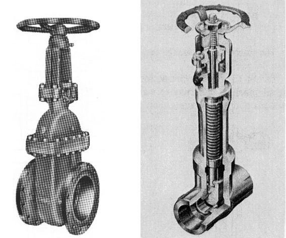
Figure 3-39. Wedge Gate with Plain Solid Wedge, Welded Bonnet, External Screw, Bellows Stem Seal, and Auxiliary Stuffing Box Seal.
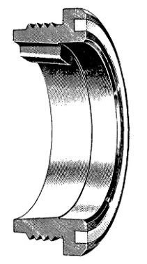
Figure 3-40. Seat of Wedge Gate Valve with PTFE Sealing Insert.
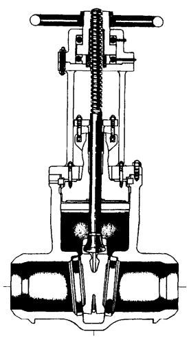
Figure 3-41. Wedge Gate Valve with Flexible Wedge, Pressure-Sealed Bonnet, External Screw.
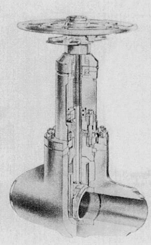
Figure 3-42. Forged Wedge Gate Valve with Pressure-Sealed Bonnet, Incorporating Flexible Wedge with Hard Faced Grooves Sliding on Machined Body Ribs.
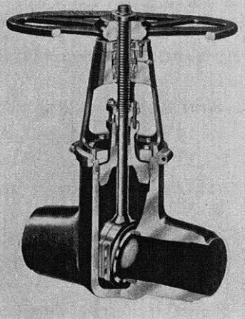
Figure 3-43. Wedge Gate Valve with Two-Piece Wedge, Pressure-Sealed Bonnet, and External Screw.
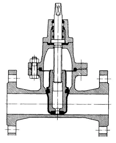
Figure 3-44. Rubber-Seated Wedge Gate Valve without Cavity in Bottom of Valve Body.
The self-aligning wedge of the valve shown in Figure 3-43 consists of two identical tapered plates that rock around a separate spacer ring. This spacer ring may also be used to adjust the wedge assembly for wear. To keep the plates together, the body has grooves in which the wedge assembly travels.
Rubber lining of the wedge, as in the valves shown in Figure 3-44 and Figure 3-45, led to the development of new seating concepts in which the seat seal is achieved in part between the rim of the wedge and the valve body. In this way, it became possible to avoid altogether the creation of a pocket at the bottom of the valve body. These valves are therefore capable of handling fluids carrying solids in suspension, which would otherwise collect in an open body cavity.
In the case of the valve shown in Figure 3-44, the wedge is provided with two stirrup-shaped rubber rings that face the rim of the wedge at the bottom sides, and the top lateral faces. When the valve is being closed, the rubber rings seal against the bottom and the sidewalls of the valve body and, by a wedging action, against the seat faces at the top.
The wedge of the valve shown in Figure 3-45 is completely rubber lined and forms part of a diaphragm, which separates the operating mechanism from the flowing fluid. When the valve is being closed, the bottom of the wedge seals against the bottom of the valve body and the body seats. The valve may also be lined with corrosion-resistant materials, and is therefore widely used in the chemical industry.
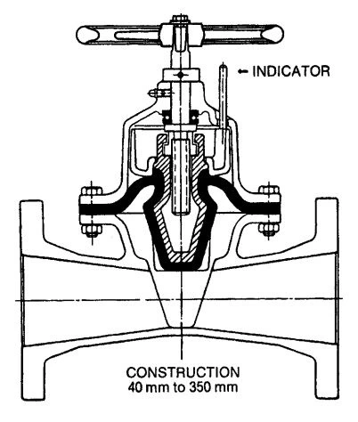
Figure 3-45. Rubber-Seated Wedge Gate Valve Without Cavity in Bottom of Valve Body.
Connection of Wedge to Stem
The wedge-to-stem connection usually consists of a T-slot in the top of the wedge, which receives a collar on the stem. According to API standard 600, this connection must be stronger than the weakest stem section so that the wedge cannot become detached from the stem while operating the valve.
The T-slot in the wedge may thereby be oriented inline with the flow pas- sage, as in the valves shown in Figure 3-38, Figure 3-39, and Figure 3-41, or across the flow passage as shown in Figure 3-36 and Figure 3-42. The latter construction permits a more compact valve body design and, there- fore, has become popular for economic reasons. Also, this construction favorably lowers the point at which the stem acts on the wedge. However, the T-slot must be wide enough to accommodate the play of the wedge in its guide, allowing also for wear of the guide.
There are also exceptions to this mode of wedge-to-stem connection, as in the valves shown in Figure 3-34 and Figure 3-37, in which the stem must carry the entire thrust on the wedge. For this reason, this construc- tion is suitable for low pressure applications only. In the valve shown in Figure 3-43, guide play is virtually absent, allowing the stem to be captured in the wedge.
Wedge Guide Design
The body guides commonly consist either of ribs, which fitinto slots of the wedge, or of slots, which receive ribs of the wedge. Figure 3-42 and Figure 3-43 illustrate these guiding mechanisms.
The body ribs are not normally machined for reason of low cost construction. However, the rough surface finish of such guides is not suited for carrying the travelling wedge under high load. For this reason, the wedge is carried on valve opening initially on the seat until the fluid load has become small enough for the body ribs to carry the wedge. This method of guiding the wedge may require considerable play in the guides, which must be matched, by the play in the T-slot for suspending the wedge on the stem.
Once the body ribs begin to carry the wedge upon valve opening, the wedge must be fully supported by the ribs. If the length of support is insufficient, the force of the flowing fluid acting on the unsupported section of the wedge may be able to tilt the wedge into the downstream seat bore. This support requirement is sometimes not complied with. On the other hand, some valve makers go to any length to ensure full length wedge support.
There is no assurance that the wedge will slide on the stem collar when opening the valve. At this stage of valve operation, there is considerable friction between the contact faces of the T-slot and stem collar, possibly causing the wedge to tilt on the stem as the valve opens. If, in addition, the fit between T-slot and stem collar is tight, and the fluid load on the disc is high, the claws forming the T-slot may crack.
For critical applications, guides in wedge gate valves are machined to close tolerances and designed to carry the wedge over nearly the entire valve travel, as in the valves shown in Figure 3-42 and Figure 3-43.
In the valve shown in Figure 3-42, the wedge grooves are hard-faced and precision-guided on machined guide ribs welded to the valve body. The wedge is permitted in this particular design to be carried by the seat for 5% of the total travel.
In the valve shown in Figure 3-43, the wedge consists of two separate wedge-shaped plates. These carry hard-faced tongues that are guided in machined grooves of the valve body. When wear has taken place in the guides, the original guide tolerance can be restored by adjusting the thickness of a spacer ring between the two wedge plates.
Valve Bypass
Wedge gate valves may have to be provided with bypass connections for the same reason described for parallel gate valves on page 77.
Pressure-Equalizing Connection
In the case of wedge gate valves with a self-aligning double-seated wedge, thermal expansion of a fluid locked in the valve body will force the upstream and downstream seatings into still closer contact and cause the pressure in the valve body cavity to rise. A similar situation may arise with soft-seated wedge gate valves in which the wedge is capable of producing an upstream seat seal. Thus, if such valves handle a liquid with high thermal expansion, or ifrevaporation of trapped condensate can occur, they may have to be provided with a pressure-equalizing connection as described for parallel gate valves on page 77.
Case Study of Wedge Gate Valve Failure
Figure 3-46 through Figure 3-48 show components of a DN 300 (NPS 12) class 150 wedge gate valve to API standard 600 that failed on first application.
The valve was mounted in a horizontal line under an angle of 45。from the vertical for ease when hand-operating a gear drive. This operating position required the wedge to ride on the body rib. Unfortunately, the guide slot in the wedge had sharp edges. As the wedge traveled on the rib, the sharp edges of the guideslot caught on the rough rib surface, causing the wedge to rotate until contacting the opposite body rib. At this stage, the wedge was jammed. Further closing effort by the valve operator produced the damage to the valve internals shown in Figure 3-46 through Figure 3-48.
Figure 3-46 shows the damage to the wedge guide that was riding on the body rib and Figure 3-47 shows the damaged body rib. Figure 3-48 shows the bent valve stem and damage to the stem surface around the stem guide bush.
Further inspection of the valve showed also that play in the wedge guides was larger than the possible travel of the wedge on the stem. Thus, the stem had to carry the wedge for part of its travel in a tilted position. Furthermore, the lengths of body rib and wedge guide were far too short to adequately support the wedge during all stages of travel.
This valve failure was not isolated but was typical for a high percentage of all installed wedge gate valves. Finally, all suspect valves had to be replaced prior to start-up of the plant.
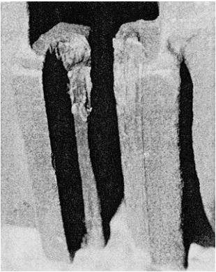
Figure 3-46. Damage to Guide Slots of Flexible Wedge Resulting from Attempted Closure of Wedge Gate Valve with Wedge Rotated and Jammed in Valve Body, Size DN 300 (NPS 12) Class 150.
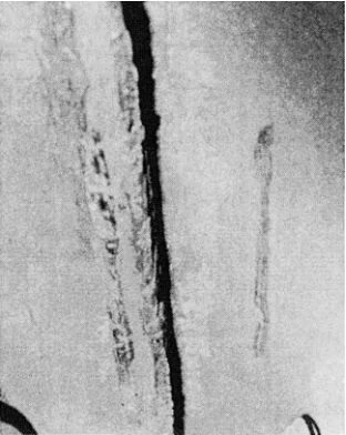
Figure 3-47. Damage to Valve Body Guide Ribs Resulting from Attempted Closure of Wedge Gate Valve with Rotated Wedge Jammed in Valve Body, Size DN 300 (NPS 12) Class 150 .
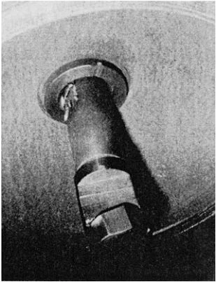
Figure 3-48. Bent Valve Stem with Damage to Stem Surface Resulting from Attempted Closure of Wedge Gate Valve with Wedge Rotated and Jammed in Valve Body, Size DN 300 (NPS 12) Class 150.
Standards Pertaining to Wedge Gate Valves
Appendix C provides a list of U.S. and British standards pertaining to wedge gate valves.
Applications
Duty:
- Stopping and starting flow
- Infrequent operation
Service:
- Gases
- Liquids
- Rubber-seated wedge gate valves without bottom cavity for fluids carrying solids in suspension
